Skip links

MİCRODET-1

Documents

Product Description

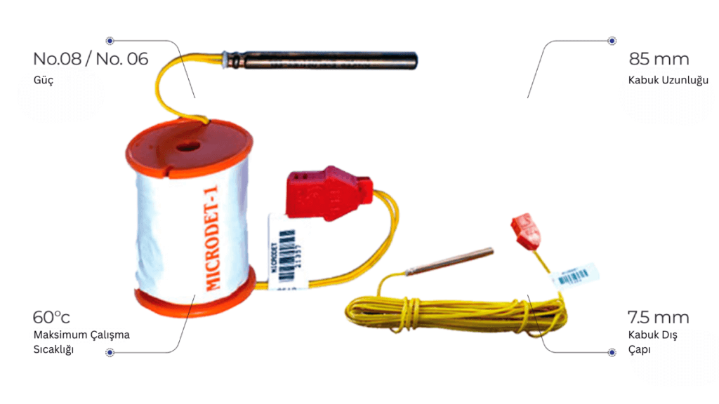
Programmable Electronic Detonator The Electronic Ignition System offers high accuracy, reliability, and programmability.

Product Technical Specifications:

Parameter Value
Shell Material Aluminum / Copper
Power No.08 / No.06
Shell Length 85 mm
Shell Outer Diameter 7.5 mm
Delay Range 0 ms – 8000 ms
Maximum Operating Temperature 60 °C
Water Resistance Excellent
Connection Cable Material Copper Coated Steel / Copper
Maximum Connection Cable Length 60 Meters
Main Conductor Wire Material (Resistance) Copper, Two-Colored (0.07 Ω/m)
Maximum Circuit Resistance 100 Ohms
Delay Accuracy Up to 500 ms: ±1 ms, Over 500 ms: ±0.2%
Packing Details:
Length Reel Size Bundle (pcs) Packaging (pcs) Box Arrangement (pcs) In Box (pcs)
1–3 m 5 10 300
4 m 5 10 240
5–9 m 5 5 150
10–28 m Disk diameter: 60 mm, Height: 92 mm 8x5x2 80
29–60 m Disk diameter: 84 mm, Height: 92 mm 6x3x2 36

Technical Details

System: The Programmable Electronic Detonator (Microdet-1) consists of an electronic circuit that controls the delay time of the trigger. The microprocessor-based circuit allows adjustment of variable delay duration. Each detonator is assigned a unique trigger ID during production. Additionally, each detonator has a specific label number, which also functions as its trigger ID. The electronic circuit includes a digital timing circuit and an energy storage device; energy is only released when the “activate” and then “fire” commands are given. The electronic detonator is connected to a connector with copper-coated steel wire. The micro logger can also be connected to this wire via the connector. The Electronic Detonator consists of the following components:
  • Electronic Chip: Controls the delay time and ensures the firing sequence is safely executed.
  • Main Charge and Primer: Made of a PETN and AS composition.
  • Connector: A plastic device that connects individual detonators to the main circuit using copper-coated steel wire. The connector allows fast connection to the main supply line.
  • Cable Reel: The lead wire longer than 10 meters is wound onto a plastic reel. The detonator is placed and fixed into the center of the reel spindle.
 
  • Micro Logger: Used to assign the delay time to the detonator and stores information such as the hole tag, detonator ID, delay, and firing order. When connected to the Microdet and the record button is pressed, it reads the detonator ID, assigns the hole tag and delay, and checks if the detonator is integrated. The assigned delay can be modified before transferring data to the digital blaster. Once all detonators are registered, the data from the micro logger is transferred to the Tester and the Blaster.
  • Network Tester: Used to check all connections, including all detonators and cables. If any connection error occurs, the corresponding hole ID is displayed on the Tester screen.
  • Digital Blaster (Micro Blaster): After all connections are completed, the blaster performs final checks and executes the blasting. It checks each detonator in sequence and confirms readiness. Once confirmed, the “activate” signal is sent, followed by another round of checks before sending the “fire” signal simultaneously to all detonators, completing the blast.
  Blasting Circuit: The circuit is completed when each detonator is assigned a unique hole number and delay time by the micro logger and is connected to the firing line (bus line) via the connector. The micro logger communicates with the digital blaster and transfers the recorded data. It is also possible to transfer this data to a computer for blasting design via software. The copper trunk cable is connected to the digital blaster positioned in a safe location. The digital blaster tests and activates each detonator individually. Once the “All Ready” signal is received, the “Fire” command is issued to complete the blast.

Storage and Operating Conditions

  • Transport and storage temperature: between -10°C and +50°C
  • Operating temperature range: -20°C to +60°C

Control Equipment

  • Must be stored in facilities with proper humidity and temperature control.
  • Micro Blaster must always be operated from a safe distance and not used as a tester.

Safety

  • The Micro Logger checks whether the detonator is integrated.
  • The Network Tester is designed not to trigger the detonator capacitor.
  • The digital blaster checks connections, leakage currents, and circuit continuity.
  • An authorization key is required to trigger the detonator.
  • The fire button is equipped with a protective cover.
  • The electronic detonator should only be used by trained personnel or engineers.

Precautions

  • Electronic detonators contain sensitive explosives and must be protected from shock, friction, and heat.
  • After the “deactivate” signal, testing must not begin before waiting at least 10 minutes.
  • If the blast does not occur, do not approach the blast site for at least 30 minutes or as per local regulations.